

Your current location:Home>>PRODUCT>>Cut off the butterfly valve
Cut off the butterfly valve
Product features:
One, use
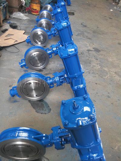
The pneumatic actuator is powered by compressed air, driving mechanism to open and close thevalve, butterfly valve isometric travel valve. The mechanism and complete the valve assembly,widely used in the field of petroleum chemical industry, metal smelting, light industry,pharmaceutical, nuclear power equipment, boiler, shipbuilding, coastal industrial and militaryscientific experiment, automatic operation as a pipeline of centralized control or remote control separately.
Two, the structure principle
When the compressed air from the left air inlet to enter the two piston cavity, the two piston separation cylinder gas chamber, both ends of the air is discharged through the exhaust holes leftin the central axis, at the same time it counterclockwise rotation of 90 degrees, the correspondingvalve also follow the counterclockwise rotation of 90 degrees open. On the other hand, in the rightintake, make the two piston closed, central gas cavity air is discharged through the vent hole rightin the center axis, and clockwise rotation of 90 degrees, the valve is shut off.
Three, installation and adjustment and manual operation (accessories)
1, according to the valve actuator or valve specifications required driving torque select corresponding. The output torque should be calibrated by the 0.4MPa actuator in air pressureunder the general data, selecting actuator torque should be greater than the required driving torque valve 25%.
2, referring to the external connection diagram, the butterfly valve or ball valve actuator output shaft head alignment into the key hole, when the valve and actuator are in the closed position, and with the corresponding bolt actuator and valve connection.
3, with actuator valve generally should be installed vertically upright in the pipeline, the actuatorcylinder direction should be consistent with the direction of the pipe. If must be level should be installed in the filter (accessories) and electromagnetic valve (accessories) converted to a vertical position. The valve body is overweight should be appropriate to increase the support, in order to avoid deformation of the body. When the installation is also hand operating mechanism (Annex)attachment to set aside a certain location for easy manual operation.
4, in order to ensure the opening and closing the valve position accurately, actuator is provided with a micro adjustment mechanism, can be micro adjusted cylinder at both ends of the adjusting bolt, to determine the accurate position of the spool. After the adjustment, must the sealing nut and a sealing pad tightly sealed, to avoid leakage. After adjustment in the above should also adjust the stroke switch (accessories) position. Adjust as needed.
5, the pneumatic actuator can be equipped with a manual operating mechanism (Annex), in emergency and special circumstances, the use of manual operating mechanism can be operated manually. Manual operation when the actuator cylinder two ventilation opening in order to reduce the resistance, convenient operation. Then the switching handle to pull hand operating mechanismcaused by manual position, can be hand wheel operation. Restore to the state automatic manualoperation is completed, switch lever handle operating mechanism of recovery of pneumatic position,connect the gas path can achieve automatic state.
Four, test and maintenance
Pneumatic actuators and valves installation is good or not directly affects the use effect, actuator.The reasonable installation is the actuator center shaft and the valve stem must be absolutelycoaxial connection and installation, reasonable. Actuator and valve before installation, the valve should torque measurement, should not exceed the actuator torque, in order to adapt to the valve using a medium environment, spherical and seal shall be dry, clean, assembly, pneumatic actuator and valve at the same time test, on the valve sealing pressure to rated pressure, actuator to the air pressure to 4~7 kg / cm 2, to switch to two inlet air inlet pneumatic actuator Pneumatic, observe the opening and closing of the valve, should not have a pause, creeping phenomenon, should switch flexible rotation, should be repeated test. Pneumatic actuator for field instruments, should beregular maintenance and repair. The actuator shall be dry, clean air, water, sewage and regularlyon the actuator corresponding with the use of air filters, lest enter solenoid valve and actuator,affecting the normal work. Under normal circumstances, should be inspected once every six months, maintenance once a year.
-2-
Five, solenoid valve control circuit diagram (accessories)
1, double electric control two position five way electromagnetic valve circuit diagram (Figure 1)
Double solenoid valve: when the solenoid valve coil D1 is energized when the two position four way electromagnetic valve or the two position five way electromagnetic valve action, A gas circuit is switched on, the compressed air enters the cylinder at both ends, to promote the two piston closed,the middle air cavity air through the B hole, discharged from the exhaust hole and the electromagnetic valve, cylinder shaft clockwise clockwise rotation of 90 DEG, complete closure of the valve action. Open the valve solenoid coil D2 through the action of an electric solenoid valve,gas path is connected with the B, the compressed air enters the cylinder middle make two piston separation, the middle air cavity air through the A hole, from the electromagnetic valve through the exhaust air outlet, complete opening the valve action.
2, a single electronic control two position five way electromagnetic valve circuit diagram (Figure 2)
Single solenoid valve: the solenoid valve is only one coil, when the solenoid valve coil is energizedsolenoid valve action, A gas circuit is switched on, the compressed air enters the cylinder at both ends, so that the two piston closed, the middle air cavity air through the B hole, discharged from the exhaust hole and the electromagnetic valve, cylinder axis counterclockwise direction of rotation 90degree, complete opening the valve action, when the power is off, then close the valve, so that thenormally closed. When the electricity power valve is closed, the valve opening, that is, normally open.
The structure and characteristics of:
1, using two JLXW1-A type micro switch, a six terminal and adjustable cam, centrally mounted on the circuit board, the micro switch circuit has been previously connected to the connection terminal.So has the advantages of reasonable design, compact structure.
For turning operation 2, through the concave wheel shaft top executive device, rotation touches twoJLXW1-A type microswitch contact with roller reed, therefore, convenient installation, make